| Home |
| My projects |
| Realizations |
| USB |
| Mecanics |
| Triks |
| Links |
| Who am I ? |
 |
| ERROR 404 |
Triks
This section contains some helpful tips for electronics hobbyists.
You can find :
- Advice on the implementation of ICs
- The recovery technique processors
- A collection of courses on PICs
- A bootloader for PIC 16F8xx with software
- ICSP programming
The realization of ICs
What is interesting for the amateur, is to realize its own ICs (it's even more interesting if we can get good quality). The realization of a printed circuit is organized into 4 stages :
Sunburn :
The engraving quality is largely dependent on the sunburn ICs. In trade, we can find a briefcase of sunshine for 60 €, but there is another solution which consists in its own exposure unit. The advantage of this second method is firstly the cost, and secondly the quality.
For my part, I decided to opt for the second method. I used 4 tubes of 43 cm to 6 € purchased piece. Then I noted the important DIMENSIONS sunstroke professionals: Find the full description in the "MECA."
In conclusion, I am very satisfied with the sunshine and I encourage all fans who wish to embark on this adventure.

|

|
| Sunburn and its timer | 4 neon UV |

|

|
| LThe bottom is painted white to the more homogeneous light. |
Neon on their attachment |
Revelation :
Once the circuit sunned, it must be before burning. For that, you have to buy the developer (preferably KF) and dilute in 1 liter of water.
The developer can be reused several times. However, care must be taken to keep away the light: for my part, I keep a bottle of milk.
So just plunge the circuit to be exposed in the bath for about thirty seconds, and you should see the copper discovery.
Engraving :
That is the real work begins. To burn, there are several solutions: the conventional method with a printmaker and ferric chloride, and acid method.
The conventional method :
You have to buy perchloride bagged or / and tin and pour into a container. It is advisable to heat the mixture (with a heater may be). To move, you can shake your hand or buy an air pump aquarium by example and a diffuser to blow bubbles.
The etching takes tens of minutes after the wear of perchlorate. Read the full description of my engraver in the "MECA."
Care must be taken not to project the perchorure on clothing or on the floor because it is a very messy product.
 Here my first printmaker bubble.  The air pump generates bubbles to accelerate the etching Here a second version of tilting printmaker. |
 Here a second version of tilting printmaker.   The engine with its link. |
The first version of engraver uses a storage bin and a commercial aquarium air pump. A plastic grid that allows the cards remain flat on the top of the bubbles.
The second version of the engraver has a removable tray that can easily put the ferric chloride into the bottle after each use. The tray is driven in a rocking motion creating a movement of ferric chloride and allowing a more uniform and rapid burning. The rocking motion is created by a rotisserie motor, coupled to a small rod.
Currently, when I still burn cards, I use the engraver tilt because it is faster to clean and store.
The acid method :
You can retouver full description of this method on the site ofXI.
.
I present this method:
Here's an interesting method on all points : the cost is low, almost zero investment, and quality. The principle is as follows : A mixture of hydrochloric acid (purchased in supermarkets) hot water and hydrogen peroxide (110 volumes, is in pharmatie) with the following proportions :
- 1 / 2 cup of hot water
- 30ml acid
- 10 ml of hydrogen peroxide
Then dip the plate revealed in the mixture, the acid attacks the blister copper engraving takes less than three minutes.
During the etching, we need to stir the mixture. For my part, I use the tilt printmaker presented above: the plate is positioned above the copper side, which helps control the burn without having to raise the IC. Note that this type of burning smell pungent due to the acid: it is advisable to ventilate the room well and wear eye protection.

LThe engraver in action !
The soldering of ICs :
To approach the professional quality and protect the copper against oxidation, it is necessary to cover the CIS with a protective layer. To achieve this, there are multiple solutions: the protective coating, tin plating cold tinning the heat gun.
The cold tinning is a process that is expensive because the product can not be used many times, and he quickly lapses: a can costs 15 € approximately and must be used quickly.
That's why I prefer the tinning heat gun: you start with a coat of paste tin (in the plumbing department), then using the heat gun, heat the IC when we will see the tab melt and deposit on copper. It must then remove excess with a sponge and foot of water, and it is ok.
Note that it is increasingly difficult to obtain pulp with lead because lead is banned: they sometimes sell a paste of lead free pewter that must heat up more and gives poorer results.

|

|

|
| Tools : | The plate ready to be heated. | Tin plate and cleaned. |
Tips :
- Dillu can paste in a little water to spread it more evenly.
- For an excellent final result, we can clean the plate with the steel wool.
The recovery of processors :
If there are many interesting compounds to be recovered, it's processors. These are parts which are relatively expensive and found in most of the appliances that surround us (VCRs, old TV, stereos ..).
When one gets a transformer, it is rare for its characterstics or printed, so we must test it. Here is a simple method: we test (off) with a multimeter the different windings (one must find strength from 0 to 1 ohms for high school and more than 10 ohms for the primary). Are identified as primary and secondary. Now the trials will be energized, so we must take precautions against the 230. It does not connect directly to the primary sector, but it interpolates a bulb 100W/230V series. This precaution when an error between primary and secondary to protect your electrical system, thus avoiding a short circuit. IT must first connect the voltmeter in AC mode 1000V on the secondary. Connect and verify that the secondary voltage is between 5 and 100V. If all goes well, the bulb should shine a bit. If it shines very hard is that there is a connection error.
If all these tests are positive, you can plug the transformer directly to the mains via a fuse and proceed to measure the voltage at the secondary level. These tests are relatively dangerous and are reserved for knowledgeable people.
Another tip : mark the secondary stress on the transformer itself so you do not have to test all your transformers whenever you are looking for one!

Lesson of PIC :

|
Lesson on 16F84 : 27 pages of comprehensive course for beginners, simple and consist. |

|
Jacquart School lessons : A quick and effective lesson of 16F84. |
All great courses Bigonoff are available on its website : www.abcelectronique.com/bigonoff/
- Bigonoff lesson on the 16F84 : impeccable quality courses, ideal for all, a very good support work with examples and clear explanations.
- Lesson Bigonoff on 16F8xx : it is the result of the previous course, but it concerns the largest PICs (Chapters 2 and 3).
- Lesson Bigonoff on 18Fxxx : it is the migration to 18F, it is advisable to read the previous courses.
PIC documentation :
Bootloader for PIC :
What is the technique of bootloader?
The technique involves sending a bootloader program to the PIC via the serial port. The PIC receives the program and wrote to iron and measure in its memory.
Why use a bootloader instead of the classic lineup?
The bootloader allows a much faster programming on 16F. Indeed, using a programmer, it takes almost 1 minute of programming, but here, 20 seconds is enough. On the other hand, there is no need to move the PIC on the programmer.
What are the disadvantages of the bootloader?
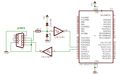
The bootloader is a program stored in the last 256 bytes of CIP. It must therefore be careful not to use them in your program (C compilers have an option to preserve DCI check this site). The bootloader needs a serial port on the PIC: we must create a small interface (see below).
First part - interface serial port on the PIC:
You can use a MAX232 for interfacing between the serial port and the PIC. However, it remains a less costly solution in the following scheme :
Second part - the program the PIC :
Pic must be programmed the first time using a timer.
I give the bootloader I developed in assembler. This version is the latest: it is able to describe the blocks up to 96 bytes, and it checks that you write in authorized areas. On the other hand, it avoids rewriting the bytes that have not changed. Indeed, this option slows down the lineup the first time, but when minor changes, the PIC is programmed in less than 5 seconds.
In the assembly file, choose the speed of the serial port, the crystal frequency and the type of PIC. If you have problems to compile the program, feel free to write me, I will send you directly to the HEX file.
Third Party : PC software :
The PC software has been developed by a friend in C + + I appreciate the way (software author: Emmanuel Durin).
GUI software :

- You must set the speed at which we work and the COM port number used.
- It remains only to press "Set" and do a reset or power to the PIC.
ICSP programming
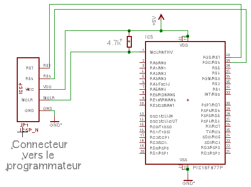
Another possible solution is to program the PIC without having to move is programming ICSP.
The technique is very simple: it connects directly to the PIC programmer. It will however make sure not to use the port RB6 and RB7 as these two lines must remain in high impedance (prohibition to connect a LED).
We can then add a small layer 5 son that connects the card to the controller.
Note : the program that I propose in category LABO, this connector is available.


